4.1Introduction to Finite Automata
Our plan is to start with a very concrete example of a finite automaton in the form of tally counters, learn how to do computation with it, and then generalize.
4.1.1(Simple) tally counters
Consider the modest tally counters that you have probably seen at entrances to bars, concerts, museums, and other venues where they are used to keep track of how many people have entered and how many have left.
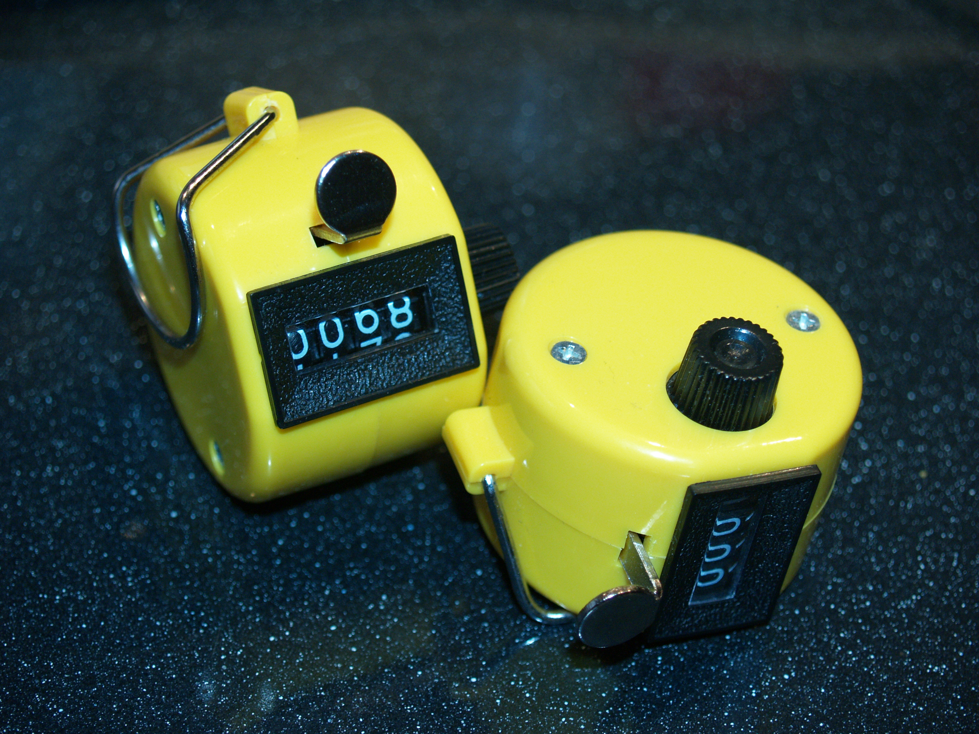
Image of a tally counter. Credit: Wikimedia Commons
The tally counter has 3 components:
A displayed number that is initially 0000, and can go up to 9999. We call this number the count.
An “increment” button on top. Pressing the button increments the number by 1 if the current count is less than 9999, and it becomes 0000 otherwise, i.e. it adds 1 modulo 10000.
A “reset” dial on the right side. The dial can be used to reset the count to 0000 by rotating it clockwise sufficiently many times.
Thus, we can view the tally counter as a device with 10000 states, whose initial state is 0, and that receives as input a sequence of “increments” and “resets”.[1]
4.1.2(Even simpler) single-digit tally counter
To make the rest of our discussion manageable, in the remainder, we focus on the state of the first digit (i.e. the rightmost digit). This is equivalent to a single-digit tally counter that operates as follows:
It has 10 states, corresponding to the numbers .
Its initial state is 0.
Let be the current state.
Incrementing changes its state to .
Resetting changes its state to 0.
We can succinctly represent the single-digit tally counter using a state transition table and a state diagram.
State transition table:
| Current state | Reset | Increment |
|---|---|---|
| (Initial) 0 | 0 | 1 |
| 1 | 0 | 2 |
| 2 | 0 | 3 |
| ⋮ | ⋮ | ⋮ |
| 9 | 0 | 0 |
State diagram:
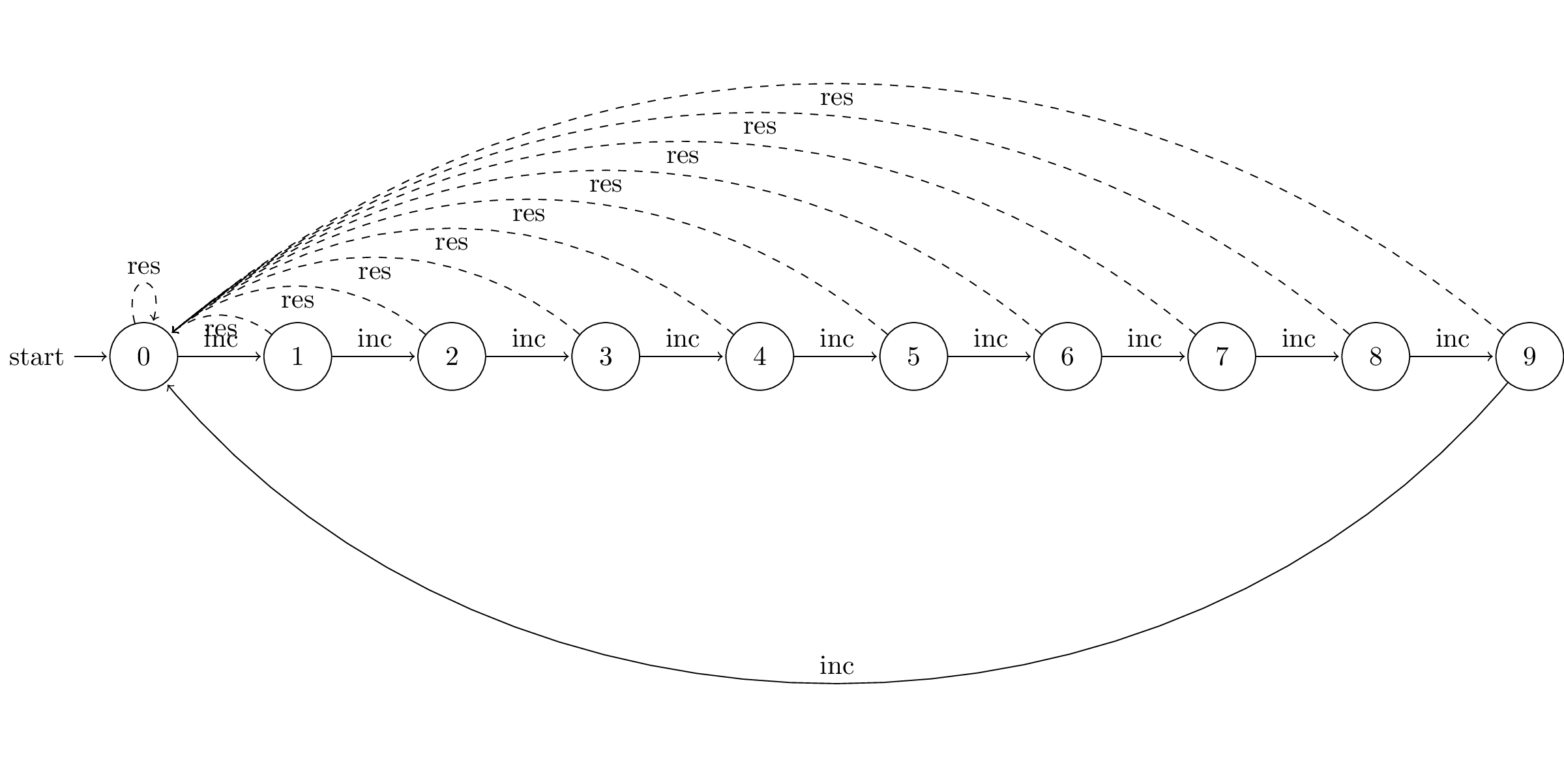
Dashed edges correspond to transitions due to “resets” and solid ones correspond to “increments”.
4.1.3Turning counters into computational devices
Let’s now turn the single-digit tally counter into a computational device that receives its input bit string as a sequence of bits, one bit at a time. There are two tasks we need to turn it into a finite automaton:
Specify how the device accepts/rejects strings.[2] In general, this is done by indicating some states as accepting states and defining an input string to be accepted if the device ends up in an accepting state at the end of the string.
Specify how it transitions between states in response to each incoming bit of the input. In particular, we need to specify a state transition table.
Let us keep things simple and suppose that the string is accepted if the final state of the tally counter is 0. Consider the following simple examples, and let’s see what the set of accepted strings are in each of these examples.
Let’s take a look at its state transition table and diagram
| Current state | 0 | 1 |
|---|---|---|
| (Initial, Accepting) 0 | 1 | 1 |
| 1 | 2 | 2 |
| 2 | 3 | 3 |
| ⋮ | ⋮ | ⋮ |
| 9 | 0 | 0 |
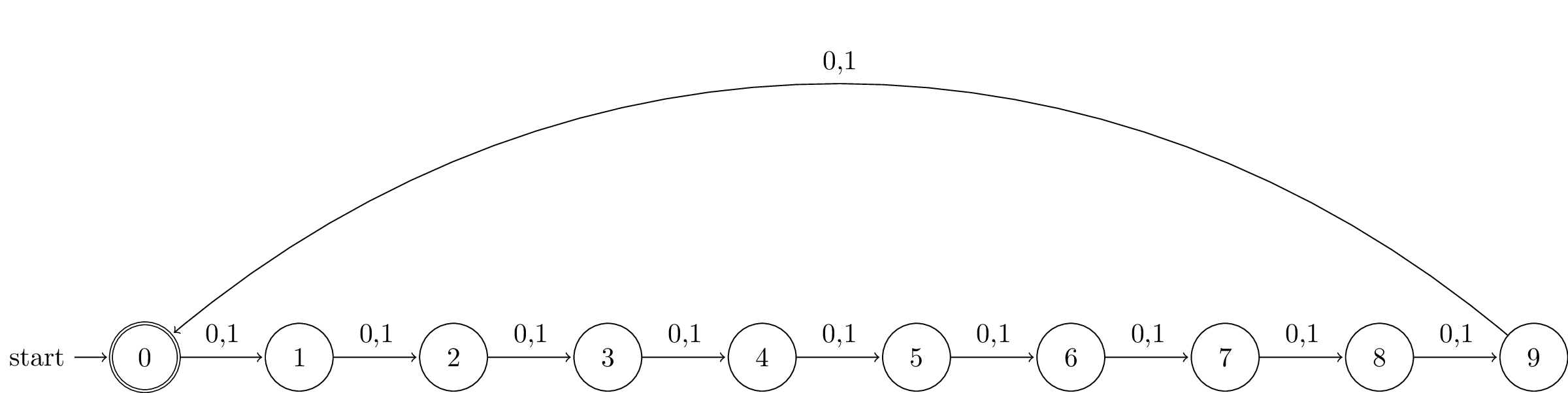
We use double circle to denote that 0 is an accepting state.
Solution to Exercise 1 #
Strings whose length is a non-negative multiple of 10.
Solution to Exercise 2 #
Strings in which the number of 1s is a non-negative multiple of 10.
For this one, it can be helpful to take a look at this Ed lesson which simulates the finite automaton.
Solution to Exercise 3 #
It is easy to see that every string ending with 0 is accepted. But these are not the only ones. Every string whose number of 1s is a non-negative multiple of 10 and has no 0s are is also accepted. In general, a string is accepted iff the number of 1s since the last-occuring 0 is a non-negative multiple of 10 (if there is no 0, then since the start of the string).
In general, from any state, we can go to any other state by using a sequence of “increments”.
4.1.4Finite automata for bit strings
Recall the state transition table for Exercise 1 the first example above.
| Current state | 0 | 1 |
|---|---|---|
| (Initial) 0 | 1 | 1 |
| 1 | 2 | 2 |
| 2 | 3 | 3 |
| ⋮ | ⋮ | ⋮ |
| 9 | 0 | 0 |
In general, we can define a finite automaton for bit strings using a state transition table with 3 columns:
Each row represents a state of the finite automaton
Column 1: name of the state
Column 2: which state to transition to if next bit is 0
Column 3: which state to transition to if next bit is 1
Here’s the formal definition of finite automata for bit strings.
4.1.5Finite automata in general
In general, we can have strings with other “alphabets”, depending on the application.
Let be a finite automaton. Consider an input string where each is a symbol of the alphabet. The finite automaton processes as follows:
Start at the start state
For each input symbol (starting from ), follow the corresponding transition: if the current state is , then go to state .
After all input symbols have been processed, it accepts the string if the final state (also called the resulting state) is an accepting state, and rejects it otherwise.
In particular, it goes through the following sequence of state transitions:
where we use the notation to mean that , i.e. the state after processing the -th symbol of the input string .
The final state is called the resulting state of . We define the notation to mean the resulting state of .
4.1.6Computation path
The state transition diagram representation gives a nice graphical representation of the sequence of state transitions that a finite automaton goes through while processing a string . In particular, we can represent the sequence
as a path in the state transition diagram that starts from (the initial state), goes to , then , and so on. Note that the path can repeat vertices.[3]
We refer to this path as the computation path of on input .
4.1.7Key features of a finite automaton
Constant memory
Memory = states and number of states is independent of input length
(Memorylessness) Behavior depends only on current state and next symbol, e.g. it does not remember how many times it has visited the current state before
Receive the input as a stream
(It ain’t over till it’s over) Does not know when the input is going to end
Observe that the tally counter has the above properties. Clearly, its memory is fixed and cannot allocate new memory.
Analogous to a program that has two phases:
(Initialisation phase) Before seeing the input, it declares the set of variables, and the set of possible values they can take. This includes a variable called IsAccept which can be either True or False.
(Input processing phase) While the stream is not empty, get next symbol and update variables. No new variables can be declared. Variables restricted to values declared in Init phase.
(Final phase) When stream is empty, return IsAccept
A more direct representation of the tally counter is as a finite automaton that receives a sequence of “increments” and “rotations” where the latter corresponds to a single dial rotation instead of several rotations that resets the count. However, the exact effect of a single dial rotation is too complicated for the purposes of our discussion.
As discussed previously in Section 3.3, we are focusing on decision problems and so we need to specify a way for the device to indicate whether it accepts an input string or not.
If you are familiar with graph theory, the path is not necessarily a simple path.